Table of Contents
Basic electronics
- Posted by:Connie
Learning about basic electronics and creating your own projects is a lot easier than you may think. In this tutorial, we’re going to give you a brief overview of common electronic components and explain what their functions are. You will then learn about schematic diagrams and how they are used to design and build circuits. And finally, you will put this information to use by creating your first basic circuit.
Get a Basic Understanding of Voltage, Current and Resistance
Current flows, resistance resists, voltage pushes.
And they all affect each other.
This is important to know to learn electronics properly.
Understand how they work in a circuit and you will have this step nailed.
But, there’s no need to dive deep into Ohm’s law – this step can be learned through simple cartoons.
Learn Electronics By Building Circuits From Circuit Diagrams
A circuit is a complete and closed path through which electric current can flow. In other words, a closed circuit would allow the flow of electricity between power and ground. An open circuit would break the flow of electricity between power and ground.
Anything that is part of this closed system and that allows electricity to flow between power and ground is considered to be part of the circuit.
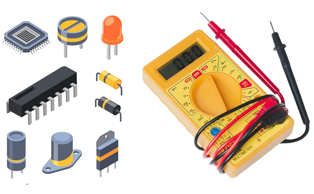
Get a Basic Understanding of These Components
Resistor
Resistors are used to resist the flow of current or to control the voltage in a circuit. The amount of resistance that a resistor offers is measured in Ohms. Most resistors have colored stripes on the outside and this code will tell you it’s value of resistance. You can use a multimeter or Digikey’s resistor color code calculator to determine the value of a resistor.
Capacitor
Capacitors store electricity and then discharges it back into the circuit when there is a drop in voltage. A capacitor is like a rechargeable battery and can be charged and then discharged. The value is measured in F (Farad), nano Farad (nF) or pico Farad (pF) range.
What Is A Circuit?
Before you design an electronic project, you need to know what a circuit is and how to create one properly.
An electronic circuit is a circular path of conductors by which electric current can flow. A closed circuit is like a circle because it starts and ends at the same point forming a complete loop. Furthermore, a closed circuit allows electricity to flow from the (+) power to the (-) ground uninterrupted.
In contrast, if there is any break in the flow of electricity, this is known as an open circuit. As shown below, a switch in a circuit can cause it to be open or closed depending on it’s position.
All circuits need to have three basic elements. These elements are a voltage source, conductive path and a load.
The voltage source, such as a battery, is needed in order to cause the current to flow through the circuit. In addition, there needs to be a conductive path that provides a route for the electricity to flow. Finally, a proper circuit needs a load that consumes the power. The load in the above circuit is the light bulb.
How To Determine A Resistor Size
Resistors are commonly used in electronics projects and it’s important to know which size to use. To find the resistor value, you need to know the voltage and the amps for your LED and battery.
A standard LED generally needs a voltage of around 2V and a current of 20mA or .02A to operate correctly. Next, you need to find out what voltage your battery is. In this example, we will be using a 9V battery. In order to determine the resistor size, we need to use a formula known as Ohm’s law as shown below.
Ohm’s Law – Resistance (R) = Voltage (V) / Current (I)
- Resistance is measured in Ohms (Ω)
- Voltage is measured in volts (V)
- Current is measured in amps (A)
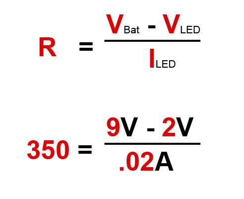
Using Ohm’s law, you need to subtract the LED voltage from the battery voltage. This will give you a voltage of 7 which needs to be divided by .02 amps from the LED. This formula shows that you will need a 350 Ω resistor.
As a note, standard resistors don’t come in 350 Ω but are available in 330 Ω which will work fine.


 Two-Way Radio Guide: Why PTT Matters?")


Comments
No data Yet